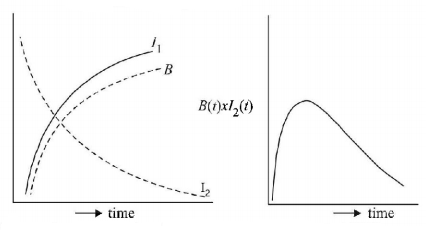
101. A coil of wire having inductance and resistance has a conducting ring placed coaxially within it. The coil is connected to a battery at time $$t = 0,$$ so that a time-dependent current $${I_1}\left( t \right)$$ starts flowing through the coil. If $${I_2}\left( t \right)$$ is the current induced in the ring, and $$B\left( t \right)$$ is the magnetic field at the axis of the coil due to $${I_1}\left( t \right),$$ then as a function of time $$\left( {t > 0} \right)$$ the product $${I_2}\left( t \right)B\left( t \right)$$
A
increases with time
B
decreases with time
C
does not vary with time
D
passes through a maximum
Answer :
decreases with time
102. A conducting circular loop is placed in a uniform magnetic field of $$0.04\,T$$ with its plane perpendicular to the magnetic field. The radius of the loop starts shrinking at $$2\,mm/s.$$ The induced emf in the loop when the radius is $$2\,cm$$ is
A
$$4.8\,\pi \,\mu V$$
B
$$0.8\,\pi \,\mu V$$
C
$$1.6\,\pi \,\mu V$$
D
$$3.2\,\pi \,\mu V$$
Answer :
$$3.2\,\pi \,\mu V$$
103. Two coils have a mutual inductance of $$0.005\,H.$$ The current changes in the first coil according to equation $$i = {i_0}\sin \omega t,{i_0} = 10\,A$$ and $$\omega = 100\,\pi \,rad/s.$$ The maximum value of emf in the second coil is
A
$$2\pi $$
B
$$5\pi $$
C
$$\pi $$
D
$$4\pi $$
Answer :
$$5\pi $$
104. Two coils of self-inductances $$2\,mH$$ and $$8\,mH$$ are placed so close together that the effective flux in one coil is completely linked with the other. The mutual inductance between these coils is
A
$$10\,mH$$
B
$$6\,mH$$
C
$$4\,mH$$
D
$$16\,mH$$
Answer :
$$4\,mH$$
105.
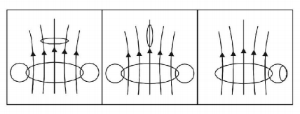
Two circular coils can be arranged in any of the three situations shown in the figure. Their mutual inductance will be

A
maximum in situation (a)
B
maximum in situation (b)
C
maximum in situation (c)
D
the same in all situations
Answer :
maximum in situation (a)
106.
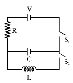
In an $$LCR$$ circuit as shown below both switches are open initially. Now switch $${S_1}$$ is closed, $${S_2}$$ kept open. ($$q$$ is charge on the capacitor and $$\tau = RC$$ is Capacitive time constant). Which of the following statement is correct ?
A
Work done by the battery is half of the energy dissipated in the resistor
B
At $$t = \tau ,\,q = \frac{{CV}}{2}$$
C
At $$t = 2\tau ,\,q = CV\left( {1 - {e^{ - 2}}} \right)$$
D
At $$t = 2\tau ,\,q = CV\left( {1 - {e^{ - 1}}} \right)$$
Answer :
At $$t = 2\tau ,\,q = CV\left( {1 - {e^{ - 2}}} \right)$$
107.
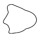
As a result of change in the magnetic flux linked to the closed loop shown in the figure, an emf $$V$$ volt is induced in the loop. The work done (joule) in taking a charge $$q$$ coulomb once along the loop is
A
$$qV$$
B
zero
C
$$2\,qV$$
D
$$\frac{{qV}}{2}$$
Answer :
$$qV$$
108. The current in self-inductance $$L = 40\,mH$$ is to be increased uniformly from $$1\,A$$ to $$11\,A$$ in 4 millisecond. The emf induced in inductor during the process is
A
$$100\,V$$
B
$$0.4\,V$$
C
$$4\,V$$
D
$$440\,V$$
Answer :
$$100\,V$$
109.
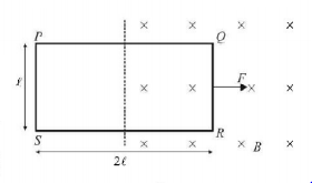
A rectangular loop $$PQRS,$$ is pulled with constant speed into a uniform transverse magnetic field by a force $$F$$ (as shown). E.m.f. induced in side $$PS$$ and potential difference between points $$P$$ and $$S$$ respectively are (Resistance of the loop = $$r$$)
A
zero, $$\frac{{Fr}}{{B\ell }}$$
B
zero, zero
C
zero, $$\frac{{Fr}}{{6B\ell }}$$
D
$$\frac{{Fr}}{{6B\ell }},\frac{{Fr}}{{6B\ell }}$$
Answer :
zero, $$\frac{{Fr}}{{6B\ell }}$$
110.
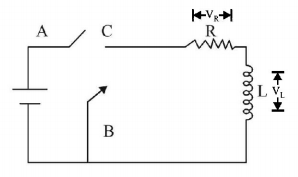
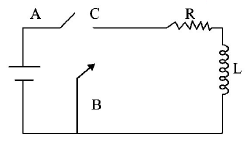
In the circuit shown here, the point $$'C'$$ is kept connected to
point $$'A'$$ till the current flowing through the circuit becomes
constant. Afterward, suddenly, point $$'C'$$ is disconnected from
point $$'A'$$ and connected to point $$'B'$$ at time $$t = 0.$$ Ratio of the
voltage across resistance and the inductor at $$t = \frac{L}{R}$$ will be
equal to:
A
$$\frac{e}{{1 - e}}$$
B
1
C
-1
D
$$\frac{{1 - e}}{e}$$
Answer :
-1
