131.
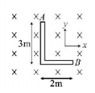
An $$L$$-shaped conductor rod is moving in transverse magnetic field as shown in the figure. Potential difference between ends of the rod is maximum if the rod is moving with velocity

A
$$4\hat i - 6\hat j\,m/s$$
B
$$ - 4\hat i + 6\hat j\,m/s$$
C
$$3\hat i + 2\hat j\,m/s$$
D
$$\sqrt {13} \,\hat i\,m/s$$
Answer :
$$3\hat i + 2\hat j\,m/s$$
132.
An equilateral triangular loop $$ABC$$ made of uniform thin wires is being pulled out of a region with a uniform speed $$v,$$ where a uniform magnetic field $${\vec B}$$ perpendicular to the plane of the loop exists. At time $$t = 0,$$ the point $$A$$ is at the edge of the magnetic field. The induced current $$\left( I \right)$$ vs time $$\left( t \right)$$ graph will be as

A


B


C


D


Answer :


133. The total charge induced in a conducting loop when it is moved in magnetic field depends on
A
the rate of change of magnetic flux
B
initial magnetic flux
C
the total change in magnetic flux
D
final magnetic flux
Answer :
the total change in magnetic flux
134. A $$0.1\,m$$ long conductor carrying a current of $$50\,A$$ is perpendicular to a magnetic field of $$1.21\,mT.$$ The mechanical power to move the conductor with a speed of $$1\,m{s^{ - 1}}$$ is
A
$$0.25\,mW$$
B
$$6.25\,mW$$
C
$$0.625\,W$$
D
$$1\,W$$
Answer :
$$6.25\,mW$$
135. A charge $$Q$$ is uniformly distributed over the surface of non-conducting disc of radius $$R.$$ The disc rotates about an axis perpendicular to its plane and passing through its centre with an angular velocity $$\omega .$$ As a result of this rotation a magnetic field of induction $$B$$ is obtained at the centre of the disc. If we keep both the amount of charge placed on the disc and its angular velocity to be constant and vary the radius of the disc then the variation of the magnetic induction at the centre of the disc will be represented by the figure :
A


B


C


D


Answer :


136.
A conducting ring of radius $$r$$ with a conducting spoke $$OA$$ is in pure rolling on a horizontal horizontal surface in a region having a uniform magnetic field $$B$$ as shown, $$v$$ being the velocity of the centre of the ring. Then the potential difference $${V_0} - {V_A}$$ is :

A
$$\frac{{Bvr}}{2}$$
B
$$\frac{{3Bvr}}{2}$$
C
$$ - \frac{{Bvr}}{2}$$
D
$$\frac{{ - 3Bvr}}{2}$$
Answer :
$$ - \frac{{Bvr}}{2}$$
137. A vertical ring of radius rand resistance $$R$$ falls vertically. It is in contact with two vertical rails which are joined at the top. The rails are without friction and resistance. There is a horizontal uniform magnetic field of magnitude $$B$$ perpendicular to the plane of the ring and the rails. When the speed of the ring is $$v,$$ the current in the top horizontal of the rail section is
A
0
B
$$\frac{{2Brv}}{R}$$
C
$$\frac{{4Brv}}{R}$$
D
$$\frac{{8Brv}}{R}$$
Answer :
$$\frac{{8Brv}}{R}$$
138. Which of the following units denotes the dimension $$\frac{{M{L^2}}}{{{Q^2}}},$$ where $$Q$$ denotes the electric charge?
A
$$Wb/{m^2}$$
B
Henry $$\left( H \right)$$
C
$$H/{m^2}$$
D
Weber $$\left( {Wb} \right)$$
Answer :
Henry $$\left( H \right)$$
139.
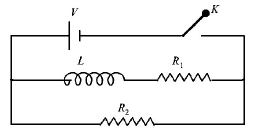
In the circuit shown below, the key $$K$$ is closed at $$t = 0.$$ The current through the battery is


A
$$\frac{{V{R_1}{R_2}}}{{\sqrt {R_1^2 + R_2^2} }}\,{\text{at}}\,t = 0\,{\text{and}}\,\frac{V}{{{R_2}}}\,{\text{at}}\,t = \infty $$
B
$$\frac{V}{{{R_2}}}\,{\text{at}}\,t = 0\,{\text{and}}\,\frac{{V\left( {{R_1} + {R_2}} \right)}}{{{R_1}{R_2}}}\,{\text{at}}\,t = \infty $$
C
$$\frac{V}{{{R_2}}}\,{\text{at}}\,t = 0\,{\text{and}}\,\frac{{V{R_1}{R_2}}}{{\sqrt {R_1^2 + R_2^2} }}\,{\text{at}}\,t = \infty $$
D
$$\frac{{V\left( {{R_1} + {R_2}} \right)}}{{{R_1}{R_2}}}\,{\text{at}}\,t = 0\,{\text{and}}\,\frac{V}{{{R_2}}}\,{\text{at}}\,t = \infty $$
Answer :
$$\frac{V}{{{R_2}}}\,{\text{at}}\,t = 0\,{\text{and}}\,\frac{{V{R_1}{R_2}}}{{\sqrt {R_1^2 + R_2^2} }}\,{\text{at}}\,t = \infty $$
140. A conductor $$AB$$ of length $$l$$ moves in $$x - y$$ plane with velocity $$\vec v = {v_0}\left( {\hat i - \hat j} \right).$$ A magnetic field $$\vec B = {B_0}\left( {\hat i + \hat j} \right)$$ exists in the region. The induced emf is
A
zero
B
$${B_0}l{v_0}$$
C
$$2{B_0}l{v_0}$$
D
$$\sqrt 2 {B_0}l{v_0}$$
Answer :
zero


