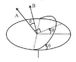
41. A rectangular coil of $$20$$ turns and area of cross-section $$25\,sq.\,cm$$ has a resistance of $$100\Omega .$$ If a magnetic field which is perpendicular to the plane of coil changes at a rate of 1000 tesla per second, the current in the coil is
A
$$1\,A$$
B
$$50\,A$$
C
$$0.5\,A$$
D
$$5\,A$$
Answer :
$$0.5\,A$$
42.
A uniform but time-varying magnetic field $$B\left( t \right)$$ exists in a circular region of radius $$a$$ and is directed into the plane of the paper, as shown. The magnitude of the induced electric field at point $$P$$ at a distance $$r$$ from the centre of the circular region

A
is zero
B
decreases as $$\frac{1}{r}$$
C
increases as $$r$$
D
decreases as $$\frac{1}{{{r^2}}}$$
Answer :
decreases as $$\frac{1}{r}$$
43.
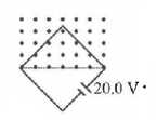
A square loop with $$2.0\,m$$ sides is perpendicular to a uniform magnetic field, with half the area of the loop in the field is shown in figure. The loop contains a $$20.0\,V$$ battery with negligible internal resistance. If the magnitude of the field varies with time according to $$B = 0.042 - 0.87\,t,$$ with $$B$$ in tesla and $$t$$ in second. The net emf of the circuit is:
A
$$20.0\,V$$
B
$$18.26\,V$$
C
$$21.74\,V$$
D
None of these
Answer :
$$21.74\,V$$
44.
As shown in the figure, $$P$$ and $$Q$$ are two coaxial conducting loops separated by some distance. When the switch $$S$$ is closed, a clockwise current $${I_P}$$ flows in $$P$$ (as seen by $$E$$) and an induced current $${I_{{Q_1}}}$$ flows in $$Q.$$ The switch remains closed for a long time. When $$S$$ is opened, a current $${I_{{Q_2}}}$$ flows in $$Q.$$ Then the direction $${I_{{Q_1}}}$$ and $${I_{{Q_2}}}$$ (as seen by $$E$$) are

A
respectively clockwise and anti-clockwise
B
both clockwise
C
both anti-clockwise
D
respectively anti-clockwise and clockwise
Answer :
respectively anti-clockwise and clockwise
45.
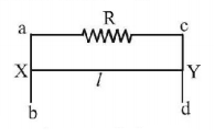
A conducting wire $$xy$$ of length $$l$$ and mass $$m$$ is sliding without friction on vertical conduction rails $$ab$$ and $$cd$$ shown in Fig. A uniform magnetic field $$B$$ exists perpendicular to the plane of the rails, $$x$$ moves with a constant velocity of
A
$$\frac{{mgR}}{{Bl}}$$
B
$$\frac{{mgR}}{{B{l^2}}}$$
C
$$\frac{{mgR}}{{{B^2}{l^2}}}$$
D
$$\frac{{mgR}}{{{B^2}l}}$$
Answer :
$$\frac{{mgR}}{{{B^2}{l^2}}}$$
46.
A small bar magnet is being slowly inserted with constant velocity inside a solenoid as shown in figure. Which graph best represents the relationship between emf induced with time

A


B


C


D


Answer :


47. The magnetic flux through a circuit of resistance $$R$$ changes by an amount $$\Delta \phi $$ in a time $$\Delta t.$$ Then the total quantity of electric charge $$q$$ that passes any point in the circuit during the time $$\Delta t$$ is represented by
A
$$q = \frac{1}{R} \cdot \frac{{\Delta \phi }}{{\Delta t}}$$
B
$$q = \frac{{\Delta \phi }}{R}$$
C
$$q = \frac{{\Delta \phi }}{{\Delta t}}$$
D
$$q = R \cdot \frac{{\Delta \phi }}{{\Delta t}}$$
Answer :
$$q = \frac{{\Delta \phi }}{R}$$
48.
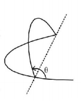
A uniform circular loop of radius $$a$$ and resistance $$R$$ is placed perpendicular to a uniform magnetic field $$B.$$ One half of the loop is rotated about the diameter with angular velocity $$\omega $$ as shown in Fig. Then, the current in the loop is
A
$$\frac{{\pi {a^2}B\omega }}{{4R}},$$ when $$\theta $$ is zero
B
$$\frac{{\pi {a^2}B\omega }}{{2R}},$$ when $$\theta $$ is zero
C
zero, when $$\theta = \frac{\pi }{2}$$
D
$$\frac{{\pi {a^2}B\omega }}{{2R}},$$ when $$\theta = \frac{\pi }{2}$$
Answer :
$$\frac{{\pi {a^2}B\omega }}{{2R}},$$ when $$\theta = \frac{\pi }{2}$$
49.
An inductor $$\left( {l = 100\,mH} \right),$$ a resistor $$\left( {R = 100\,\Omega } \right)$$ and a battery $$\left( {E = 100\,V} \right)$$ are initially connected in series as shown in the figure. After a long time the battery is disconnected after short circuiting the points $$A$$ and $$B.$$ The current in the circuit $$1\,ms$$ after the short circuit is

A
$$\frac{I}{{eA}}$$
B
$$eA$$
C
$$0.1\,A$$
D
$$1\,A$$
Answer :
$$\frac{I}{{eA}}$$
50.
An electron moves on a straight line path $$XY$$ as shown. The $$abcd$$ is a coil adjacent in the path of electron. What will be the direction of current, if any induced in the coil?
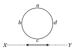
A
$$abcd$$
B
$$adcb$$
C
The current will reverse its direction as the electron goes past the coil
D
No current induced
Answer :
No current induced
