Question
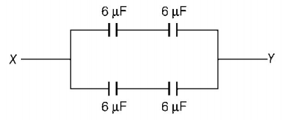
The effective capacitance between points $$X$$ and $$Y$$ of figure shown is
The effective capacitance between points $$X$$ and $$Y$$ of figure shown is

A.
$$6\mu F$$
B.
$$12\mu F$$
C.
$$18\mu F$$
D.
$$24\mu F$$
Answer :
$$6\mu F$$
Solution :
The given circuit can be redrawn as,

It is a balanced Wheatstone’s bridge $$\left( {{\text{as}}\,\frac{{{C_{AB}}}}{{{C_{BD}}}} = \frac{{{C_{AC}}}}{{{C_{CD}}}} = \frac{6}{6}} \right).$$
So, potential of $$B$$ and $$C$$ are equal and a $$6\mu F$$ capacitor between $$B$$ and $$C$$ is ineffective. The simplified circuit is shown as below.

Capacitors of $$6\mu F$$ and $$6\mu F$$ in upper arms are in series order, so
$${{C'}_{{\text{e}}{{\text{q}}_{\text{1}}}}} = \frac{{6 \times 6}}{{6 + 6}} = \frac{{36}}{{12}} = 3\mu F$$
Similarly, $$6\mu F$$ and $$6\mu F$$ in lower arms are in series order, so
$${{C''}_{{\text{e}}{{\text{q}}_{\text{2}}}}} = \frac{{6 \times 6}}{{6 + 6}} = 3\mu F$$
Now, $${{C'}_{{\text{e}}{{\text{q}}_{\text{1}}}}}$$ and $${{C''}_{{\text{e}}{{\text{q}}_{\text{2}}}}}$$ are in parallel, hence
$$\eqalign{ & {C_{{\text{net}}}} = {{C'}_{{\text{e}}{{\text{q}}_{\text{1}}}}} + {{C''}_{{\text{e}}{{\text{q}}_{\text{2}}}}} \cr & = 3 + 3 = 6\mu F \cr} $$
The given circuit can be redrawn as,

It is a balanced Wheatstone’s bridge $$\left( {{\text{as}}\,\frac{{{C_{AB}}}}{{{C_{BD}}}} = \frac{{{C_{AC}}}}{{{C_{CD}}}} = \frac{6}{6}} \right).$$
So, potential of $$B$$ and $$C$$ are equal and a $$6\mu F$$ capacitor between $$B$$ and $$C$$ is ineffective. The simplified circuit is shown as below.

Capacitors of $$6\mu F$$ and $$6\mu F$$ in upper arms are in series order, so
$${{C'}_{{\text{e}}{{\text{q}}_{\text{1}}}}} = \frac{{6 \times 6}}{{6 + 6}} = \frac{{36}}{{12}} = 3\mu F$$
Similarly, $$6\mu F$$ and $$6\mu F$$ in lower arms are in series order, so
$${{C''}_{{\text{e}}{{\text{q}}_{\text{2}}}}} = \frac{{6 \times 6}}{{6 + 6}} = 3\mu F$$
Now, $${{C'}_{{\text{e}}{{\text{q}}_{\text{1}}}}}$$ and $${{C''}_{{\text{e}}{{\text{q}}_{\text{2}}}}}$$ are in parallel, hence
$$\eqalign{ & {C_{{\text{net}}}} = {{C'}_{{\text{e}}{{\text{q}}_{\text{1}}}}} + {{C''}_{{\text{e}}{{\text{q}}_{\text{2}}}}} \cr & = 3 + 3 = 6\mu F \cr} $$

