101.
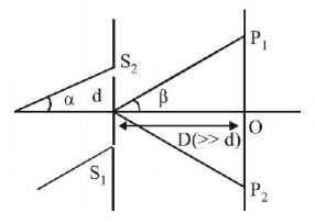
In $$YDSE$$ distance between the $${S_1}$$ and $${S_2}$$ is $$d.$$ $${P_1}$$ and $${P_2}$$ are two points equidistance from $$O$$ at an angular position $$\beta $$ as shown. A parallel beam of monochromatic light is incident at an angle $$\alpha $$ on the slits. Then the ratio of path difference at $${P_1}$$ and $${P_2}$$ is:

A
$$\cot \frac{{\alpha - \beta }}{2}\cot \frac{{\alpha + \beta }}{2}$$
B
$$\tan \frac{{\alpha + \beta }}{2}\cot \frac{{\alpha - \beta }}{2}$$
C
$$\sin \frac{{\alpha + \beta }}{2}\cos \frac{{\alpha - \beta }}{2}$$
D
$$\tan \frac{{\alpha - \beta }}{2}\cot \frac{{\alpha + \beta }}{2}$$
Answer :
$$\tan \frac{{\alpha - \beta }}{2}\cot \frac{{\alpha + \beta }}{2}$$
102.
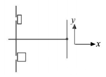
In $$YSDE,$$ both slits are covered by transparent slab. Upper slit is covered by slab of $$R.I.$$ 1.5 and thickness $$t$$ and lower is covered by $$R.I.$$ $$\frac{4}{3}$$ and thickness $$2t,$$ then central maxima

A
shifts in $$+ve$$ $$y$$ -axis direction
B
shifts in $$-ve$$ $$y$$ -axis direction
C
remains at same position
D
may shift in upward or downward depending upon wavelength of light
Answer :
shifts in $$-ve$$ $$y$$ -axis direction
103. In a Young's double slit experiment, slits are separated by $$0.5\,mm,$$ and the screen is placed $$150\,cm$$ away. A beam of light consisting of two wavelengths, $$650\,nm$$ and $$520\,nm,$$ is used to obtain interference fringes on the screen. The least distance from the common central maximum to the point where the bright fringes due to both the wavelengths coincide is:
A
$$9.75\,mm$$
B
$$15.6\,mm$$
C
$$1.56\,mm$$
D
$$7.8\,mm$$
Answer :
$$7.8\,mm$$
104.
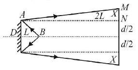
A point source of light $$B$$ is placed at a distance $$L$$ in front of the centre of a mirror of width $$'d’$$ hung vertically on a wall. A man walks in front of the mirror along a line parallel to the mirror at a distance $$2\,L$$ from it as shown in fig. The greatest distance over which he can see the image of the light source in the mirror is

A
$$\frac{d}{2}$$
B
$$d$$
C
$$2\,d$$
D
$$3\,d$$
Answer :
$$3\,d$$
105. Yellow light is used in a single slit diffraction experiment with slit width of $$0.6\,mm.$$ If yellow light is replaced by $$X$$ - rays, then the observed pattern will reveal,
A
that the central maximum is narrower
B
more number of fringes
C
less number of fringes
D
no diffraction pattern
Answer :
no diffraction pattern
106. In the ideal double - slit experiment, when a glass-plate (refractive index 1.5) of thickness t is introduced in the path of one of the interfering beams (wave - lenght $$\lambda $$ ), the intensity at the position where the central maximum occurred previously remains unchanged. The minimum thickness of the glass-plate is
A
$$2\,\lambda $$
B
$$\frac{{2\,\lambda }}{3}$$
C
$$\frac{{\lambda }}{3}$$
D
$$\lambda $$
Answer :
$$2\,\lambda $$
107.
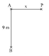
A radio transmitting station operating at a frequency of $$120\,MHz$$ has two identical antennas that radiate in phase. Antenna $$B$$ is $$9\,m$$ to the right of antenna $$A.$$ Consider point $$P$$ at a horizontal distance $$x$$ to the right of antenna $$A$$ as shown in Fig. The value of $$x$$ and order for which the constructive interference will occur at point $$P$$ is

A
$$x = 14.95\,m,n = 2$$
B
$$x = 5.6\,m,n = 2$$
C
$$x = 1.65\,m,n = 3$$
D
$$x = 0,n = 3.6$$
Answer :
$$x = 5.6\,m,n = 2$$
108. To demonstrate the phenomenon of interference, we require two sources which emit radiation
A
of nearly the same frequency
B
of the same frequency
C
of different wavelengths
D
of the same frequency and having a definite phase relationship
Answer :
of the same frequency and having a definite phase relationship
109.
In the figure shown in a $$YDSE,$$ a parallel beam of light is incident on the slits from a medium of refractive index $${n_1}.$$ The wavelength of light in this medium is $${\lambda _1}.$$ A transparent slab of thickness $$t$$ and refractive index is put infront of one slit. The medium between the screen and the plane of the slits is $${n_2}.$$ The phase difference between the light waves reaching point $$O$$ (symmetrical, relative to the slit) is

A
$$\frac{{2\pi }}{{{n_1}{\lambda _1}}}\left( {{n_3} - {n_2}} \right)t$$
B
$$\frac{{2\pi }}{{{\lambda _1}}}\left( {{n_3} - {n_2}} \right)t$$
C
$$\frac{{2\pi {n_1}}}{{{n_2}{\lambda _1}}}\left( {\frac{{{n_3}}}{{{n_2}}} - 1} \right)t$$
D
$$\frac{{2\pi {n_1}}}{{{\lambda _1}}}\left( {{n_3} - {n_2}} \right)t$$
Answer :
$$\frac{{2\pi }}{{{n_1}{\lambda _1}}}\left( {{n_3} - {n_2}} \right)t$$
110.
Figure shows two coherent sources $${S_1} - {S_2}$$ vibrating in same phase. $$AB$$ is an irregular wire lying at a far distance from the sources $${S_1}$$ and $${S_2}.$$ Let $$\frac{\lambda }{d} = {10^{ - 3}}.\angle BOA = {0.12^ \circ }.$$ How many bright spots will be seen on the wire, including points $$A$$ and $$B.$$

A
2
B
3
C
4
D
more than 4
Answer :
2
