11.
In the circuits $$\left( a \right)$$ and $$\left( b \right)$$ switches $${S_1}$$ and $${S_2}$$ are closed at $$t = 0$$ and are kept closed for a long time. The variation of current in the two circuits for $$t \geqslant 0$$ are roughly shown by figure (figures are schematic and not drawn to scale) :

A


B


C


D


Answer :


12. A small signal voltage $$V\left( t \right) = {V_0}\sin \omega t$$ is applied across an ideal capacitor $$C$$ :
A
Current $$I\left( t \right),$$ lags voltage $$V\left( t \right)$$ by $${90^ \circ }.$$
B
Over a full cycle the capacitor $$C$$ does not consume any energy from the voltage source.
C
Current $$I\left( t \right)$$ is in phase with voltage $$V\left( t \right).$$
D
Current $$I\left( t \right)$$ leads voltage $$V\left( t \right)$$ by $${180^ \circ }.$$
Answer :
Over a full cycle the capacitor $$C$$ does not consume any energy from the voltage source.
13. An $$ac$$ voltage is applied to a resistance $$R$$ and an inductor $$L$$ in series. If $$R$$ and the inductive reactance are both equal to $$3\Omega ,$$ the phase difference between the applied voltage and the current in the circuit is
A
$$\frac{\pi }{6}$$
B
$$\frac{\pi }{4}$$
C
$$\frac{\pi }{2}$$
D
zero
Answer :
$$\frac{\pi }{4}$$
14. A sinusoidal voltage $$V\left( t \right) = 100\sin \left( {500t} \right)$$ is applied across a pure inductance of $$L = 0.02\,H.$$ The current through the coil is:
A
$$10\cos \left( {500t} \right)$$
B
$$ - 10\cos \left( {500t} \right)$$
C
$$10\sin \left( {500t} \right)$$
D
$$ - 10\sin \left( {500t} \right)$$
Answer :
$$ - 10\cos \left( {500t} \right)$$
15. The primary and secondary coils of a transformer have 50 and 1500 turns respectively. If the magnetic flux $$\phi $$ linked with the primary coil is given by $$\phi = {\phi _0} + 4t,$$ where $$\phi $$ is in weber, $$t$$ is time in second and $${\phi _0}$$ is a constant, the output voltage across the secondary coil is
A
$$90\,V$$
B
$$120\,V$$
C
$$220\,V$$
D
$$30\,V$$
Answer :
$$120\,V$$
16. A circuit has a resistance of $$12\,ohm$$ and an impedance of $$15\,ohm.$$ The power factor of the circuit will be
A
0.4
B
0.8
C
0.125
D
1.25
Answer :
0.8
17. In a series $$LCR$$ circuit, the difference of the frequencies at which current amplitude falls to $$\frac{1}{{\sqrt 2 }}$$ of the current amplitude at resonance is
A
$$\frac{R}{{2\pi L}}$$
B
$$\frac{R}{{\pi L}}$$
C
$$\frac{2R}{{\pi L}}$$
D
$$\frac{3R}{{2\pi L}}$$
Answer :
$$\frac{R}{{2\pi L}}$$
18. The potential differences across the resistance, capacitance and inductance are $$80\,V,40\,V$$ and $$100\,V$$ respectively in an $$L-C-R$$ circuit. The power factor of this circuit is
A
0.4
B
0.5
C
0.8
D
1.0
Answer :
0.8
19. In a transformer, number of turns in the primary coil are 140 and that in the secondary coil are 280. If current in primary coil is $$4A,$$ then that in the secondary coil is
A
$$4 A$$
B
$$2 A$$
C
$$6 A$$
D
$$10 A$$
Answer :
$$2 A$$
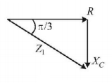
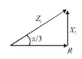
20. In an electrical circuit $$R,L,C$$ and an $$a.c.$$ voltage source are all connected in series. When $$L$$ is removed from the circuit, the phase difference between the voltage the current in the circuit is $$\frac{\pi }{3}.$$ If instead, $$C$$ is removed from the circuit, the phase difference is again $$\frac{\pi }{3}.$$ The power factor of the circuit is :
A
$$\frac{1}{2}$$
B
$$\frac{1}{{\sqrt 2 }}$$
C
1
D
$$\frac{{\sqrt 3 }}{2}$$
Answer :
1


